• Home
  • About Us
    About Us Certifications Business Areas Download Center FAQ
  • Products
    Range of Current and Potential Transformers TC - Low Voltage TC - Medium Voltage TP - Low Voltage TP - Medium Voltage Medium Voltage Transformers Low Voltage Transformers Transformers for Special Applications Renewable energy Hospital Systems K-factor transformers Power Systems Power Systems - Low Voltage Power Systems - Medium Voltage Rectifiers Download Center
  • Services
  • Career
  • Content
  • Contact
Products
We operate nationwide in the delivery of complete global solutions in the low and medium voltage area, which aim to meet the most diverse needs of our customers.
Contact us
Products > K-factor transformers > K-factor Transformers
This type of transformer is designed to support an additional load, represented by the high level of harmonic distortion existing in the installation. It has galvanic isolation between primary and secondary, with electrostatic shielding. It has special constructional characteristics that protect the transformer from current harmonics that cause losses and overheating in the windings of the transformers. The K-factor is a constant that indicates the transformer capacity to supply non-linear loads (for example, induction furnaces, motor speed variators, rectifiers, inverters, nobreaks, etc.) and support harmonic currents without exceeding its operating temperature.
Materials available for download:
REQUEST A PRICE QUOTATION
To request the contact of our team, just leave your details below:
Feature Technical information Applications
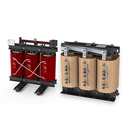
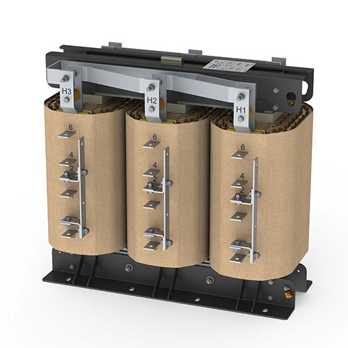
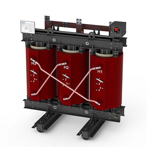
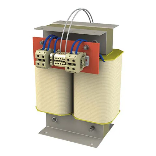
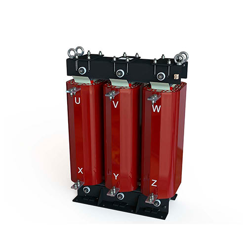
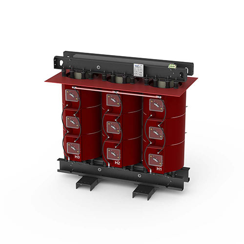
Transformers with K-factor Classification

Nowadays, in industrial workplaces, the proliferation of solid-state devices (lighting reactors, motor drive and control systems, communications equipments, and other DC motor loads) have created some relevant problems for specification engineering, contractors and business owners. The non-linear nature of the power supplies of models with switching by solid state systems, generate harmonic currents which, in turn, generate additional losses, which make transformers (some of these are large losses within the windings and some are closer to the surface) and the system neutrals overheat and be destroyed.

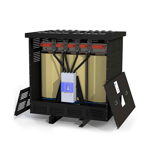
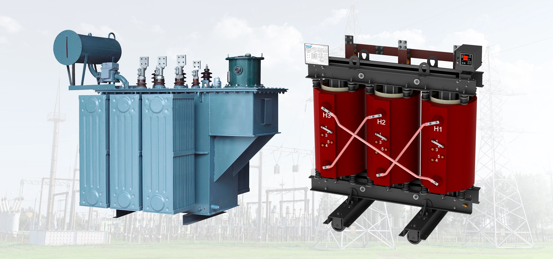
Effect of harmonics on dry-type transformers

There are several situations that may create conditions for harmonic problems in transformers, including the equipment addition to an existing electrical system, or the addition of enhancement facilities or expansions to an existing power source. Transformers with K-factor specifications are designed to reduce the heating effects of harmonic currents created by non-linear loads. The K-factor rating, assigned to a transformer, is an index of the transformer's ability to support a harmonic index in its load current, remaining within its operating temperature limits. A K-factor specific rating indicates that a transformer can supply, in addition to the nominal KVA load output, a load of a specified amount of harmonic index. In 1990, UL (Underwriters Laboratories) developed the method of calculating K-factor rating to evaluate the ability of transformers to support the harmonic effects. The K-factor does not mean that the transformer can eliminate the harmonics. The UL test is oriented to the heating of the windings, due to the general non-linear loads and overheating of the neutral conductor.

There are two methods of calculating the K-factor:
- The UL method
- The standardised method

The UL method is based on the 鈥渞ms鈥 effective rated current of the transformer. It is generally used when the effective current is measured or measurable, and is defined as:


Where:
h = harmonic order;

Ih (pu) = rms current of the harmonic expressed in pu (per unit) of the effective rated current of the transformer.

The standardised method is based on the fundamental load current. Harmonic measurements are often made with a harmonic analyzer. Most harmonic analyzers have the output responses of the harmonics in pu (values per unit) of the fundamental current. In consequence, the method would be used. The standardised method is defined as follows:

Where:
Fundamental current in pu (the 1st harmonic = 100%);

Here is an example of the two methods for the same harmonic spectrum of data. For example, we assume that the measures were taken to obtain (pu):
Up to now, industrial literature and comments refer to a limited number of K-factor ratings: K-1, K-4, K-9, K-13, K-20, K-30, K-40.

In theory, a transformer could be designed for other K-factor assessments among these values, as well as for higher values. The commonly referenced classifications are in accordance with ANSI/IEEE C57.110-1986 as follows:

K-1: This is the assessment of any conventional transformer that is designed to support only the heating effects of normal losses and additional eddy losses, resulting from 60Hz with the transformer loaded with sinusoidal current. Such a unit may or may not be designed to support the additional harmonic heating in its load current.

K-4: A transformer with this rating was designed to provide nominal KVA, without overheating, to a load provided by 100% of normal 60Hz frequency, sinusoidal current in the fundamental, and:

- 16% of fundamental current as the 3rd harmonic current;
- 10% of the fundamental current as 5th;
- 7% of the fundamental current as 7th;
- 5.5% of the fundamental current as the 9th;
- Minor percentages through the 25th harmonic.
The number "4" indicates its ability to support four times the eddy current losses of a K-1 transformer.
K-9: A K-9 transformer can support 163% of the harmonic load of a K-4 transformer.
K-13: A K-13 transformer can accommodate 200% of the harmonic load of a K-4 transformer.
K-20, K-30, K-40: The highest number of each of these K-factor ratings indicates the ability to work with successively larger amounts of harmonic load indexes without overheating.
The table below gives the example of K-factor loads

LOAD 鈥 K-FACTOR
Lighting with discharge lamps - K-4
UPS with optional inlet filter - K-4
Welding machines - K-4
Induction heating equipment - K-4
PLCs and solid-state controllers (other than variable frequency drives). - K-4
Telecommunication Equipment (for example, PBX) - K-13
UPS without inlet filters - K-13
Supply of general multiwire receptacles, in areas with health-care instruments and school classrooms, etc. - K-13
Circuit sources with multiwire receptacles for inspection and testing equipment in productive sectors or production lines - K-13
Loads of computer servers (Mainframe) - K-20
Solid-state drives for motors (variable frequency drives) - K-20
Supply of circuits with receptacles in important safety areas and rooms for hospital surgery and recovery - K-20

* Re-written with permission from EDI Magazine
The K-factor must be clearly marked on the identification plate of the transformer.
Temperature class B(130潞 C) or F (155潞 C)
There are several situations that may create conditions for harmonic problems in transformers, including the equipment addition to an existing electrical system, or the addition of enhancement facilities or expansions to an existing power source. Transformers with K-factor specifications are designed to reduce the heating effects of harmonic currents created by non-linear loads.
See more
Separation Transformer for Medical IT System
Learn more
Autotransformers
Learn more
Low voltage inductors/reactors
Learn more
Residry庐 Dry-type Transformers
Learn more
VPI Phase Transformer
Learn more
K-factor Transformers
Learn more
Medium Voltage Inductors/Reactors
Learn more
Current transformer for measurement
Learn more
Current transformer for protection
Learn more
Potential Transformer
Learn more
Encapsulated phase-shifting transformer
Learn more
TSA15TPA-TSA15TPB
Learn more
TSA25TPA-TSA25TPB
Learn more
Isolator Transformers
Learn more
Single-phase control transformer
Learn more
Single-phase power transformer
Learn more
3-phase control transformer
Learn more
TSA15TCH
Learn more
Learn more
Learn more
Learn more
Learn more
Tamura Power Link Line
Learn more
Oil-Immersed Current and Voltage Transformers
Learn more
WHAT DO OUR CUSTOMERS SAY?
I am grateful for Tamura's service, through its professionals who, in all stages of the process of our order, showed great professionalism, competence and elegance. We are very happy with this first experience with your company and we would like it to mark the beginning of a partnership between our companies.
CEZAR T.
Technical Manager, Technology Sector
The reason why we sought Tamura Brasil, was for the quality, reliability and safety of the products.
ALMIR
Buyer, Industrial Sector
Tamura serves us efficiently, has extremely high quality merchandise at a fair price and I recommend it to all of you who are thinking of buying, especially since our time is scarce, we need to be very dynamic, and Tamura becomes a company developed in this sense because it assists us whenever necessary.
RONALDO
Representative, Energy Sector
Download Center
  • Catalogues
  • Flyers
  • Manual
Multimedia Center
  • Digital Tour
  • Power Systems
Follow us on the social networks!
/tamurabrasil
Content
Mais Recentes
O que 茅 um Transformador de Pot锚ncia? Tudo o que Voc锚 Precisa Saber
Introdu莽茫o Para entender o papel crucial de um transformador de pot锚ncia, 茅 essencial compreender o conceito b谩sico de energia el茅trica e sua import芒ncia na transmiss茫o e distribui莽茫o eficientes. A energia el茅trica 茅 a for莽a que impulsiona praticamente todas as atividades industriais e dom茅sticas, e o transformador 茅 o dispositivo que garante que essa energia chegue… Continuar lendo O que 茅 um Transformador de Pot锚ncia? Tudo o que Voc锚 Precisa Saber
O que diferencia os transformadores de baixa, m茅dia e alta tens茫o?
O Objetivo deste texto 茅 mostrar para voc锚 quais s茫o as caracter铆sticas que diferenciam esses transformadores e quais s茫o as suas principais aplica莽玫es.
Transformadores para energia renov谩vel
Para que a produ莽茫o de energia limpa seja bem-sucedida, o uso de transformadores para energia renov谩vel 茅 de fundamental import芒ncia.
Diferen莽as entre transformadores a seco e a 贸leo
Um transformador se distingue por v谩rias caracter铆sticas, uma delas 茅 seu modo de resfriamento, que pode ser a 贸leo ou a seco, este artigo explica de forma clara a diferen莽a entre um transformador a seco e um transformador a 贸leo.
ORIGEM HIST脫RICA DO TRANSFORMADOR
Em 1831, Michael Faraday e Joseph Henry comprovaram, o conceito de eletro铆m茫s e as propriedades de indu莽茫o eletromagn茅tica. Saiba mais...
O que 茅 um transformador
Fundamentalmente falando, o transformador 茅 um dispositivo que converte a energia el茅trica em um n铆vel de tens茫o alternada a outro n铆vel de tens茫o alternada por meio da a莽茫o de um campo magn茅tico, de modo que sua classifica莽茫o se d谩 de acordo com as rela莽玫es: Transformador Elevador; Transformador rebaixador; transformador isolador. A publica莽茫o explica de forma t茅cnica para engenheiros iniciantes e compradores da ind煤stria possam compreender de forma b谩sica o que 茅 este equipamento el茅trico.
Tamura – NOTA T脡CNICA
Em cumprimento ao previsto no art. 2潞, 搂 3潞 do Decreto n掳 11.795/2023 a Empresa Indusul Industria de Transformadores Ltda e Industria Sul Brasil de Transformadores Ltda divulga o Relat贸rio de Transpar锚ncia Salarial, esclarecendo que referido relat贸rio est谩 equivocado em raz茫o de n茫o utilizar crit茅rios claros e transparentes quanto aos sal谩rios e remunera莽玫es, bem como… Continuar lendo Tamura – NOTA T脡CNICA
Transformador Monof谩sico: Uma Pe莽a Fundamental Seguran莽a e Efici锚ncia do sistema el茅trico
Os transformadores monof谩sicos s茫o dispositivos el茅tricos fundamentais que desempenham um papel crucial em diversas aplica莽玫es para seguran莽a e efici锚ncia do sistema el茅trico. Embora possam passar despercebidos, esses dispositivos desempenham um papel essencial na distribui莽茫o de energia el茅trica e na adapta莽茫o de tens玫es para diferentes necessidades. Neste artigo, exploraremos a utilidade, caracter铆sticas gerais, aplica莽玫es e benef铆cios… Continuar lendo Transformador Monof谩sico: Uma Pe莽a Fundamental Seguran莽a e Efici锚ncia do sistema el茅trico
Ver mais
Contact
  • SANTA CATARINA PLANT
    Rua das Ind煤strias, 251, Distrito Industrial Zeferino Kuklinski
    Massaranduba - Santa Catarina - CEP 89108-000
    55 47 3307 1700
  • MINAS GERAIS PLANT
    Rua Maria Andrade Moreira, 20, Fam铆lia Andrade, Santa Rita do Sapuca铆
    Minas Gerais - CEP 37540-000
    55 47 3307 1700
Stay tuned with the news
Be part of our community and stay on top of the news that come up here
Share it with the socialnetworks:
/tamurabrasil
Home
About Us
  • Certifications
  • Business Areas
Products
Services
Download Center
Career
Sales agents
FAQ
Privacy Policy
Contact
Opening hours
Monday to Friday
7:30 am to 12:00 pm
1:00 pm - 5:18 pm

Contact:
55 47 3307 1700
vendas@tamurabrasil.com

2025 - TAMURA CORPORATION
All righs reserved.
Back to start

Somos credenciados nos parceiros:

Logo do Banco Nacional de Desenvolvimento Econ么mico e Social

Tamura Brasil

Unidade Santa Catarina - CNPJ: 01.390.877/0001-07

Unidade Minas Gerais (Matriz) - CNPJ: 08.018.660/0001-01

Unidade Minas Gerais (Filial) - CNPJ: 08.018.660/0002-92